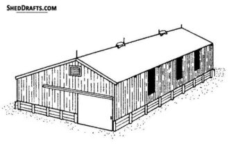
40×60 Large Pole Barn Plans
It is possible to construct a large 40×60 pole barn outbuilding on your land within some weeks by utilizing these blueprints. The structure utilizes pressure-treated laminated posts, engineered roof trusses, structural girts, and purlins.
The post-frame construction method provides great load distribution, keeps material use limited, and allows for future modifications such as additional doors, or insulation upgrades. It is recommended to build on a flat, well-drained site, that is compliant with local building codes and snow load requirements.
Stage 1: Site Preparation and Layout
Excavate the building site to a level grade within ±1 inch across the 60 ft span. Provide a minimum slope of 1% away from the structure for surface water runoff. Compact the subgrade using a vibratory plate compactor or roller. The subgrade should have a minimum bearing capacity of 1500 psf.
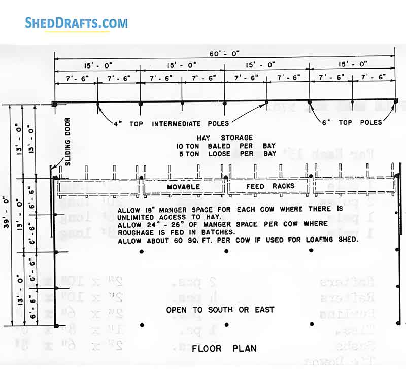
Layout
Using a builder’s level or laser level, mark the four building corners forming a 40 ft × 60 ft rectangle. Verify squareness by applying the 3-4-5 (or 6-8-10) triangle method or by checking diagonal measurements — the diagonals must be equal (approximately 72 ft 1 inch). Mark post centerlines at 10 ft intervals along each long side (total 7 posts per side including corners).
Drive survey stakes or batter boards outside the perimeter and use string lines to represent the building outline at grade height.
Spread ¾″ minus crushed gravel over the compacted subgrade to a uniform thickness of 4 inches. Rake level and compact using a vibratory plate compactor.
Concrete Slab
If a concrete floor is needed, install 6 mil vapor barrier film over the gravel base. Place #3 rebar grid at 24-inch spacing in both directions.
Pour 4 inches of 4000 psi concrete mix. Use a screed board to level the surface, followed by a bull float. Allow initial set, then finish with steel trowel for smooth surface or broom finish for slip resistance. Cut control joints at 12 ft intervals to prevent cracking.
Stage 2: Foundation and Post Installation
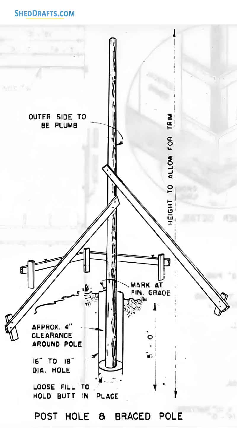
Excavate post holes using a power auger or manual digger. Diameter: 18 inches; depth: 4 ft (below frost line where applicable). Ensure hole bottoms are flat and compacted.
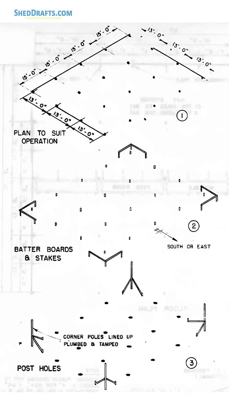
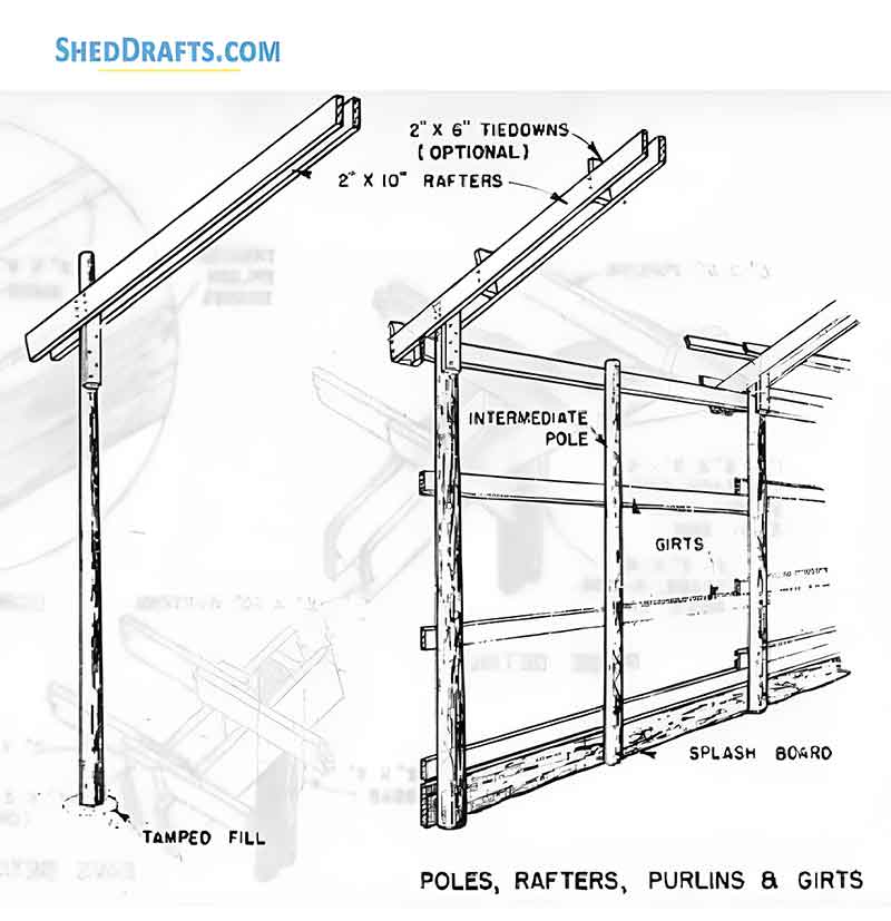
Set 6×6 pressure-treated posts into holes with a temporary bracing system. Verify plumb alignment in both directions using a post level. Maintain consistent post spacing at 10 ft on center along both eaves.
Pour approximately 6 inches of concrete footing at the bottom of each hole. Once footing sets slightly, fill around post with remaining concrete up to 3 inches below finished grade. Backfill remainder with compacted gravel for drainage.
Attach 2×8 treated skirt board along the base of the wall, spanning between posts, using ½″ × 6″ lag screws. The skirt board functions as a splash plank and bottom girt to anchor wall steel panels. Ensure the top edge of skirt board is level around the perimeter.
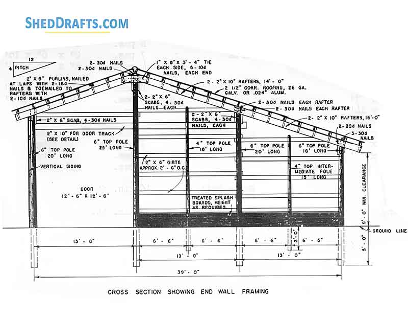
Stage 3: Wall Framing and Girts
Install 2×6 wall girts horizontally between posts. Standard spacing is 24 inches on center vertically, starting from the top of the skirt board up to the top plate elevation. Fasten using 16d galvanized nails or #10 screws through girt ends into posts.
Alternate girt placement “inset” or “on face” depending on siding method. For metal siding, face-mount girts are preferred to provide a continuous plane for sheathing.
Install 2×8 top plates along the eave line, aligned flush with the outer post face. Secure with two ½″ carriage bolts per post connection. This plate supports roof truss loads and transfers them to the posts.
For door and window openings, construct framed headers using doubled 2×8 or engineered LVL beams as required by load calculation.
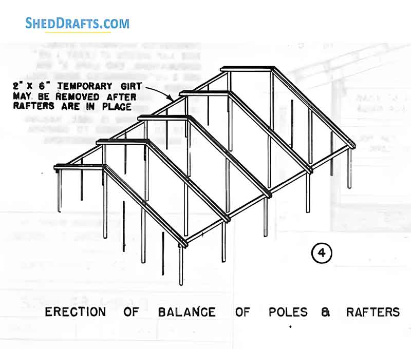
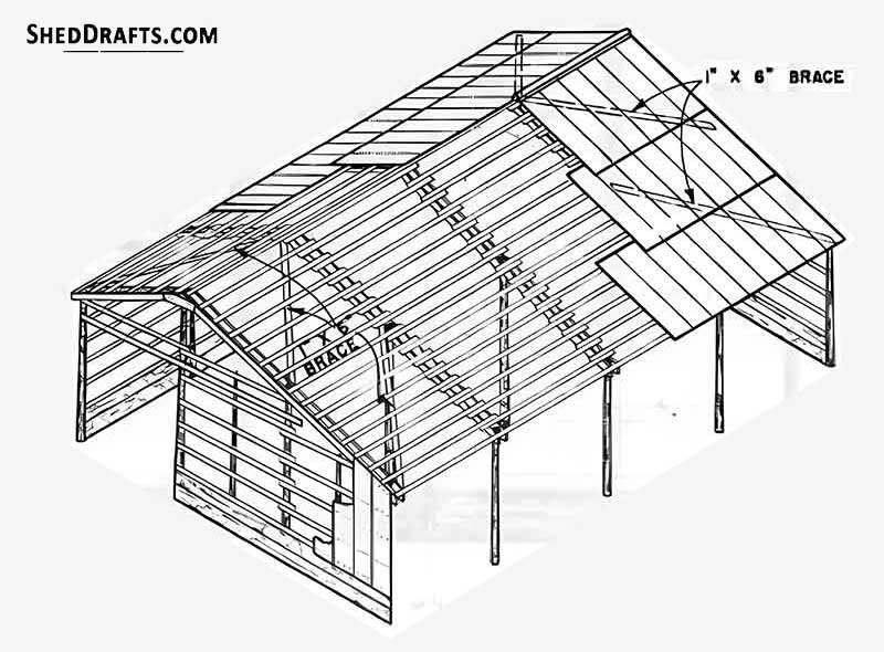
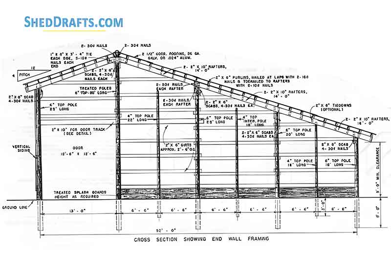
Stage 4: Roof Framing
Lift pre-fabricated trusses into position using a mechanical lift or crane. Trusses are spaced 6 ft on center along the 60 ft length, bearing directly on the top plate. Secure each truss with Simpson truss brackets and hurricane ties to prevent uplift.
Ensure truss spacing is exact to plan dimensions; use temporary lateral bracing during installation to maintain alignment.
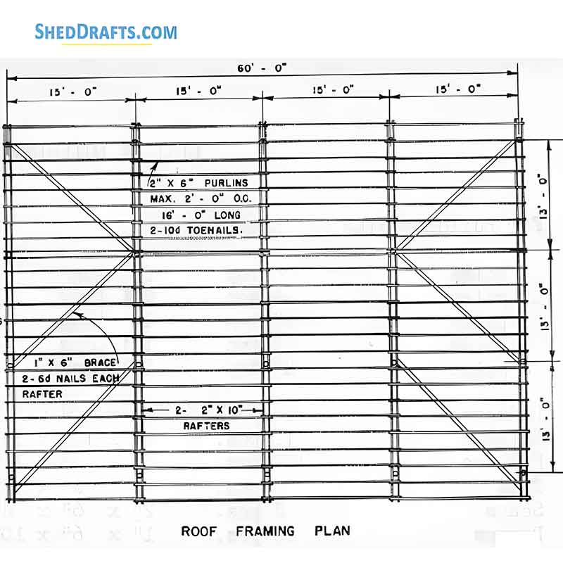
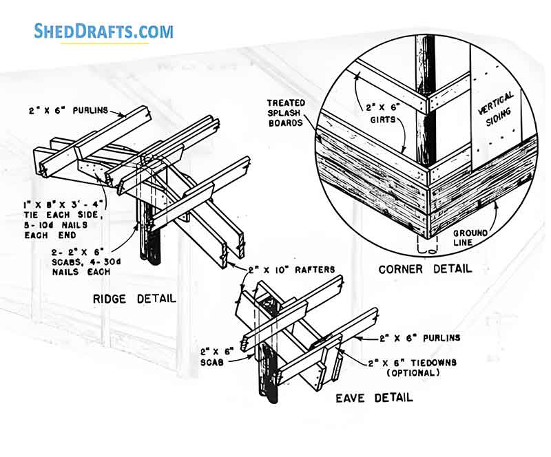
Install 2×4 purlins perpendicular to trusses, 24 inches on center, spanning from eave to ridge. Attach with two 16d nails or screws per bearing point. Stagger joints for continuous load transfer.
Install additional diagonal bracing or purlin blocking at ridge and eaves to prevent racking.
Roof Overhangs
If overhangs are specified, install fascia boards and fly rafters at gable ends. Nail the sub-fascia boards to truss ends, and then secure the soffit backing for future trim.
Stage 5: Roof Sheathing and Metal Roofing Installation
Lay synthetic roofing underlayment or felt paper over the purlins, starting from the eave and overlapping each course by at least 6 inches. Secure using cap nails or staples at 12-inch spacing.
Metal Panel Installation
Position 29-gauge corrugated steel panels perpendicular to the trusses, beginning at one gable end. Ensure the first panel is square to the eave and overhangs the edge by 1 inch. Attach using #10 × 1½″ self-drilling roofing screws with neoprene washers through the flat portion of the panel into each purlin.
Lap adjacent panels by one corrugation, sealing overlaps with butyl tape to prevent capillary water intrusion. Continue across the roof, alternating screw alignment for uniform appearance.
Ridge and Trim
Install ridge cap along the peak, overlapping roofing panels by at least 6 inches at each end. Fasten using matching roofing screws through pre-drilled holes.
Install eave trim, rake trim, and gable trim as detailed in blueprints, ensuring all laps are sealed with tape or sealant.
Stage 6: Wall Sheathing and Siding
Install vertical 29-gauge steel siding panels starting from one corner. Panels should overlap by one rib and extend from the bottom of the skirt board to the eave line. Attach panels using 1½″ self-tapping screws through every second corrugation into girts.
At door and window openings, cut panel openings with metal snips or a circular saw fitted with a metal-cutting blade. Install J-trim and corner trim to finish edges.
Install horizontal or diagonal closure panels at gable ends, overlapping roof panels to create a weather-tight seal.
Stage 7: Doors and Windows Installation
Install the top door track on the header above the opening using lag screws spaced 12 inches on center. Assemble the door frame using pre-cut 2×4 framing members or steel tubing per the kit instructions. Attach door panels and hang rollers onto the track.
Install bottom door guide rail to maintain door alignment. Adjust rollers for smooth travel.
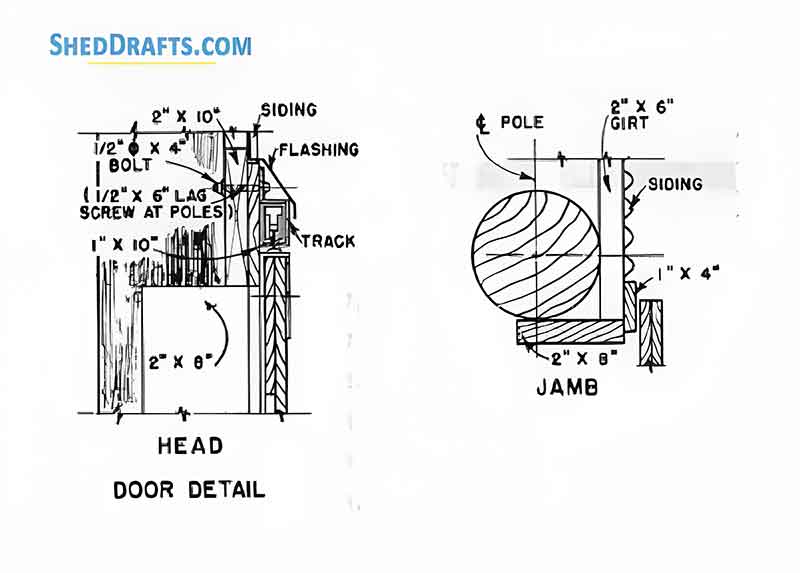
Cut opening to dimensions 3′ × 7′ with proper header support. Install pre-hung steel door unit, plumb and level. Secure jamb with shims and screws through the hinge and strike side. Apply caulking between jamb and siding.
Windows
Position window frames in pre-cut openings, ensuring proper sill slope for drainage. Fasten through flanges with corrosion-resistant screws. Apply butyl tape and flashing around perimeter to ensure watertight seal.
Stage 8: Structural Bracing and Final Checks
Add diagonal knee bracing between posts and trusses using 2×6 lumber at 45° angle to resist lateral loads. Install X-bracing in wall bays if required for wind resistance.
Check that all posts are plumb, girts and purlins are securely fastened, and all fasteners are tightened to manufacturer specifications. Verify that the roof panel overlaps and flashing joints for complete weatherproofing.
Check that the doors are properly aligned and operate smoothly.
Materials List
Structural Lumber and Posts
- (16) 6×6 pressure-treated southern yellow pine posts, 14 ft length, grade #2 or better
- (2) 2×8 skirt boards (bottom girt) pressure-treated, 60 ft length each side
- (60) 2×6 wall girts, 12 ft length (horizontal wall members between posts)
- (50) 2×4 roof purlins, 12 ft length
- (20) 2×8 top plates for wall tie and truss bearing ledge
- (30) 2×6 blocking members for intermediate bracing and wall corner reinforcement
Roof System
- (10) Engineered roof trusses, 4:12 pitch, 40 ft clear span, designed for 40 psf snow load
- (50) 2×4 purlins (roof sheathing support), spaced 24 inches on center
- 29-gauge corrugated steel roofing panels, color-coated, 3 ft wide × 10–12 ft length
- 1 ridge cap, 60 ft length total
- Eave trim and rake trim, total 120 linear feet
Fasteners and Hardware
- (10 bags) 80 lb concrete mix per post hole
- (1,000) #10 × 3″ coated structural screws
- (600) #10 × 1½″ roofing screws with neoprene washers
- (20) Simpson Strong-Tie truss-to-post metal hangers
- (16) Galvanized post base anchors (if required)
- (16) Galvanized uplift anchors
- (6) Steel strap tension ties for corner reinforcement
- (2 lbs) 16d galvanized nails for girts and purlins
- (2 lbs) 8d nails for sheathing and trim fastening
Doors and Windows
- (1) 12 ft × 10 ft sliding barn door assembly (steel-clad)
- (1) 3 ft × 7 ft steel personnel door
- (2) 3 ft × 4 ft fixed-frame windows with flanges
Floor (optional)
- Crushed gravel (¾″ minus), 4-inch compacted depth (approximately 15 cubic yards)
- Optional: 4-inch concrete slab, 4000 psi mix, with #3 rebar grid at 2 ft centers
Miscellaneous
- Vapor barrier film (6 mil polyethylene)
- Butyl tape sealant for roofing and window joints
- Closed-cell spray foam or fiberglass batt insulation (for climate control)
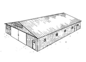
This pole barn provides approximately 2,400 square feet of open interior space that can be used for storing agricultural equipment, vehicle, or turned into a workshop. When constructed with proper foundation anchoring, engineered trusses, and corrosion-resistant fasteners, this barn will have a service life of well over 40 years with minimal maintenance.
Framing-to-Finish Roadmap: DIY Guides For Every Step of The Build