30×30 Two Car Garage Plans: Costs & Framing Guide
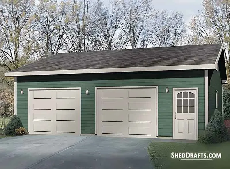
Our 30×30 two car garage shed plans have assisted many DIYers craft a spacious vehicle storage area in 6 weekends.
This project needs advanced skills due to the need for pouring a reinforced concrete foundation and hoisting heavy LVL headers. Examine the length of diagonals right after making the wall framework to ensure it is perfectly square.
Key Takeaways
Watch your anchor bolt placement like a hawk during the concrete pour. If a single 1/2-inch anchor bolt lands dead-center where a 2×4 bottom plate stud intersection occurs, you will be forced to core-drill or notch your framing plates.
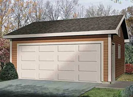
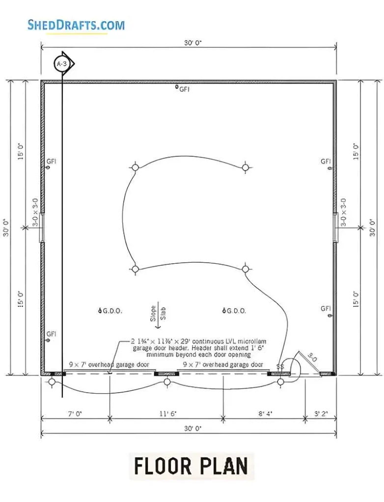
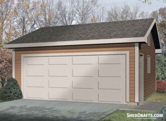
Style & Footprint – 30′ x 30′ gable roof garage with a square 900 sq. ft. foundation print.
Highlight Specs – 4:12 roof pitch, Two 9’x7’ high overhead bays, paired with a 3’x6’8” residential man-door on the front elevation, 14′-9.5″ total peak height from grade, wall and roof framing set at 16″ O.C.
What Fits Inside – Two full-sized crew-cab pickup trucks or large SUVs side-by-side. Up to 8 ATVs or 10 zero-turn lawn tractors with enough rear clearance for heavy workbenches and floor-standing tool chests.
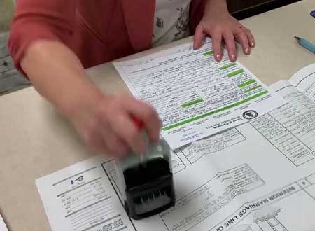
Permit Status – Full municipal and structural building permits required.
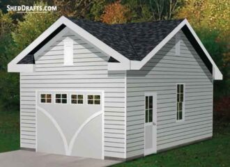
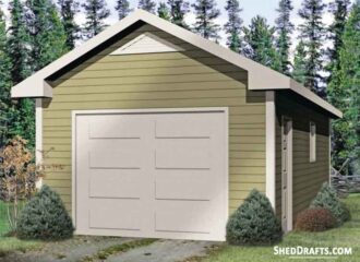
30×30 Two Car Garage Plan With Architectural Layout & Elevations
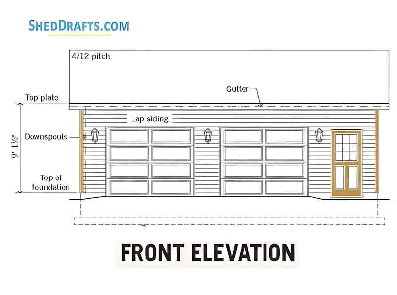
These blueprints deliver approximately 10,800 cubic feet of internal volume. You can store materials vertically, install heavy-duty shelving, or explore mezzanine storage without sacrificing valuable floor space.
Along the eaves, 2×8 rake boards and vented soffits create clean architectural lines while supporting continuous airflow through the roof assembly.
You need a sufficiently wide, level building site with proper drainage. Consider the 4:12 roof pitch and the direction of runoff to prevent water from flooding neighboring property or eroding the soil around your foundation.
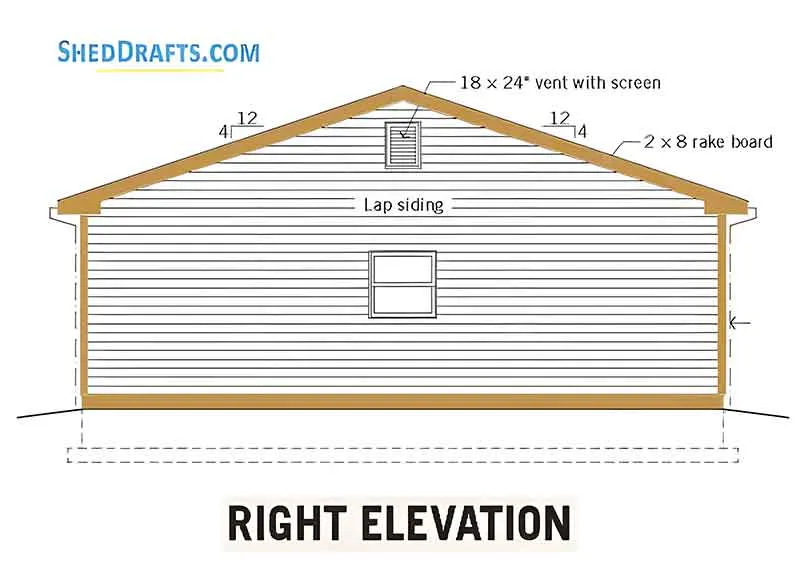
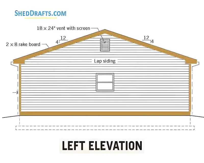
Side-yard setbacks must accommodate the full 30-foot building length and any projected eave overhangs. Check local zoning rules, easements, and setback requirements before finalizing the site plan.
Install an appropriate weather-resistive barrier over the exterior wall sheathing to help prevent wind-driven rain from reaching the framing while allowing the wall assembly to manage water vapor as designed.
The design also includes 18″ x 24″ vented gable louvers and 30″ x 30″ side-wall windows that provide daylight and support airflow.
If you plan to run fuel-powered equipment or work with dust-producing machinery, install additional ventilation. Do not rely on natural airflow alone to control hazardous fumes or airborne contaminants.
Foundation Designing & Monolithic Slab Specifications
This garage uses an 8-inch-thick poured concrete foundation wall supported by a substantial 12″ x 24″ concrete footing. That continuous footing is heavily reinforced with two #4 steel rebars running its entire perimeter to bridge minor soil irregularities and distribute structural weight evenly.
Our monolithic perimeter design eliminates traditional wood floor joists entirely, opting instead for the unyielding stability of a direct-pour slab.
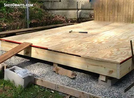
The floor itself consists of a 4-inch concrete slab poured directly over 4 inches of compacted gravel and a heavy-duty vapor barrier. This monolithic slab-on-grade foundation is fully capable of supporting thousands of pounds of vehicle and machinery weight without cracking or settling.
Poured Concrete Slab With Stem Wall Architecture
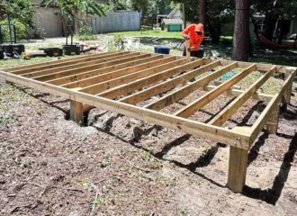
The most frequent mistake I see DIYers make on large-format slabs is failing to square up the foundation form boards diagonally. If your form is out by even a quarter-inch corner-to-corner, your wall plates will bind, your roof trusses will skew, and hanging pre-hung doors later will become an absolute nightmare.
A stem wall also raises the wood framing above the surrounding ground, helping protect the bottom plates from splashback and ground moisture. This separation is essential for preventing premature wood decay.
During foundation construction, pay close attention to the connection between the concrete and the wood framing. The concrete stem wall provides a substantial anchoring surface, but its ability to resist wind uplift depends on properly designed anchor bolts, sill plates, and connections throughout the structure.
Your location determines how deep the foundation footings must extend to resist frost-related soil movement.
Depending on local conditions, footings may need to extend approximately 12 inches below grade in some southern regions or as deep as 48 inches in colder northern areas. Actual requirements vary by jurisdiction, elevation, soil conditions, and local climate.
Soil conditions matter just as much. Before placing the 4 inches of compacted gravel, determine whether the existing soil can support the proposed structure. Some sites require additional compaction, soil replacement, or engineered fill.
Wall Framing With Overhead Door Header & Roof Specs
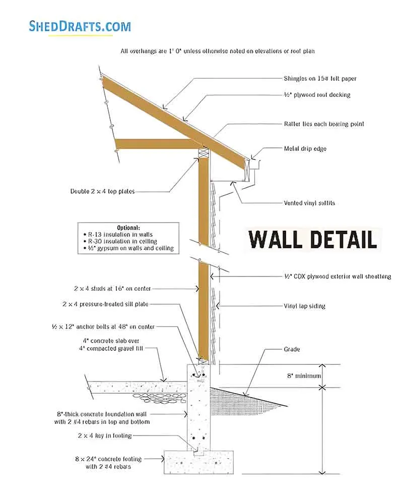
The walls are constructed using high-grade 2×4 framing studs spaced strictly at 16 inches on-center, creating a dense vertical grid that distributes roof loads evenly down to the stem wall.
The wind load tolerance of this building relies heavily on continuous tied-down structural integrity, utilizing metal hurricane ties at every rafter-to-wall connection and heavy-duty anchor bolts embedded deeply into the concrete stem wall during the initial pour.
These continuous steel ties lock the roof framing, wall studs, and foundation into a singular, unified shape capable of resisting high winds that attempt to lift the roof deck or push the expansive wall surfaces inward.
Wall Stud Engineering Along With Roof Pitch Dynamics
The 16-inch O.C. wall framing layout is a key part of the design. It provides regular support for the exterior siding and interior wall finishes while helping align wall framing with the roof structure.
When laying out 16-inch O.C. wall studs, do not rely on repeated tape measurements alone. Instead, mark the stud locations carefully and consistently. Snap chalk lines across the plates where appropriate, and use a framing square to transfer each mark accurately. Marking the top and bottom plates together helps keep stud locations aligned and improves sheathing installation.
A laser transit level is critical for shooting grades across the foundation footprint and keeping your double top plates dead-level over long wall runs. Even slight framing errors can compound across a 30-foot wall. Out-of-plumb corners and uneven plates can make sheathing and garage door installation much more difficult.
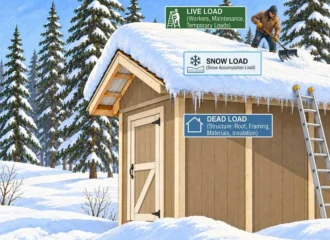
The 4:12 roof pitch is engineered to handle regional light-to-moderate snow loads up to 30 PSF, ensuring that heavy winter accumulations slide off or distribute evenly without overstressing the top chords of the roof framing.
At the same time, the shallow slope provides enough aerodynamic slope to prevent wind from catching underneath the eaves and peeling the roof deck away from its framing.
For a build of this size and complexity, ditch your standard cordless framing nailer and invest in a pneumatic clipped-head or full-round nailer hooked directly to a high-output twin-stack compressor. You will be driving thousands of fasteners through dense engineered lumber and thick framing members, and a cordless tool simply cannot maintain the rapid cycle rate and driving force required without overheating or constantly swapping batteries.
Rigging Massive LVL Headers To Avoid Common Pitfalls
Installing the specified 2-3/4″ x 11-7/8″ continuous laminated veneer lumber (LVL) headers above the garage door openings is one of the most demanding parts of this build.
These engineered beams can be heavy and difficult to control. Do not attempt to lift them manually by yourself.
Use an appropriate lifting system, such as a properly configured material lift, or enlist qualified equipment operators using suitable machinery. A telehandler may be appropriate when site conditions and equipment capacity allow. Temporary supports must also be designed and positioned correctly.
Vertical Overhead Clearances and Perimeter Wall Capacity
With over 9 feet of clearance in the intended interior area, you can plan ceiling-mounted storage racks, overhead lighting grids, and chain hoists where the structural framing and load calculations permit.
Never attach heavy equipment to roof framing without confirming its load capacity and the required connections.
The 30′ x 30′ footprint also provides approximately 120 linear feet of perimeter wall before accounting for openings. That gives you substantial space for shelving, French cleats, lumber racks, pneumatic hose reels, workbenches, and parts bins.
DIY Budget Reality, Materials & Timelines
Material price can range from $22 to $32 per square foot, translating to roughly $20,000 to $29,000. Labor costs can exceed $55,000 based on local rates.
Acting as your own general contractor and performing the labor yourself can eliminate much of the contractor labor markup. However, you still need to budget for equipment rentals, material transport, bulk fasteners, waste, and specialized tools.
A telehandler or other lifting equipment may be necessary for safely positioning heavy structural components.
I recommend adding a 10% contingency to your initial budget. This reserve helps cover unexpected lumber price changes, hardware upgrades, material waste, and equipment rental costs.
One option is to use engineered LP SmartSide panel siding instead of installing individual lap siding boards over standard 7/16-inch OSB wall sheathing.
Depending on the selected system and installation method, engineered panel siding may reduce installation labor by approximately 15%. It can also reduce the number of individual boards, joints, and fastening operations required.
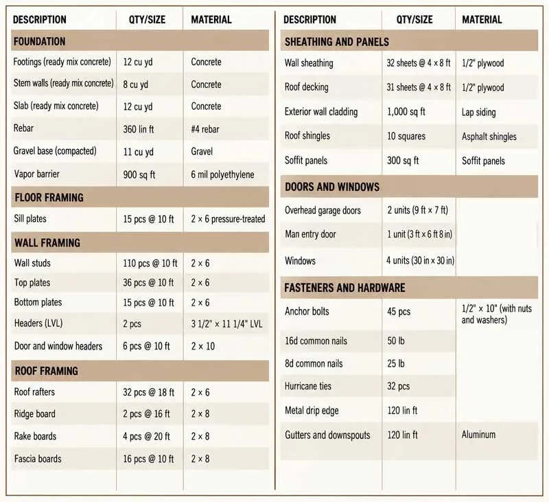
Materials List
6-Weekend Build Timeline And Construction Phasing
Plan on roughly 180 to 240 total labor hours for the complete build. An experienced, motivated two-person core build team with additional helpers during heavy-lifting phases can navigate the structural phases using this baseline 6-weekend schedule:
Weekend 1 (Days 1–2) – Complete site excavation, set perimeter formwork, lay sub-base gravel, tie steel reinforcement rebar, and pour the 12″ x 24″ concrete footings and 8-inch foundation walls. Allow proper cure time before driving heavy loads onto the perimeter.
Weekend 2 (Days 3–4) – Pour and power-trowel the 4-inch reinforced concrete floor slab over compacted gravel and vapor barrier. Set anchor bolts, treat edge joints, and lay treated sill seals and pressure-treated sill plates once the concrete achieves initial cure.
Weekend 3 (Days 5–6) – Craft 16″ O.C. wall stud layout, assemble wall sections flat on the slab, build and secure the massive continuous 2-3/4″ x 11-7/8″ LVL headers over garage door bays, and recruit a 4- to 6-person crew to raise, plumb, brace, and tie top plates together.
Weekend 4 (Days 7–8) – Hoist engineered roof trusses into place (using a crane or multi-person lift team), set temporary bracing, secure bottom chords and hurricane ties, nail down 1/2″ roof decking sheathing, and apply felt paper/ice-and-water shield with drip edge flashing.
Weekend 5 (Days 9–10) – Finish shingle installation across the 4:12 roof deck, install 18″ x 24″ gable end louvers and side windows, wrap the entire wall assembly in weather-resistive house wrap, and fit 2×8 rake boards and soffit trim.
Weekend 6 (Days 11–12) – Mount the dual 9′ x 7′ overhead garage doors, hang the 3′ x 6’8″ entry man-door, install lap or panel siding, seal all exterior joints with high-grade sealant, and execute final paint or stain application.

Framing-to-Finish Roadmap: DIY Guides For Every Step of The Build