How To Wire a Shed for Electricity: Code-Compliant DIY Guide
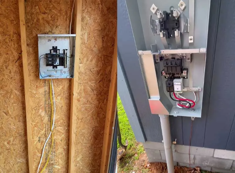
A tripped 20-amp breaker and a ruined $1,200 air compressor taught me the absolute value of proper planning twenty years ago.
Running a high-draw tool on a thin 16-gauge extension cord pulled across 120 feet of wet lawn drops line voltage down to 94 volts under load.
Motors stall and internal thermal cutouts destroy themselves. Bringing clean, dedicated utility power out to a shed requires moving beyond temporary cords and treating your structure as a fully compliant detached sub-yard.
Key Takeaways
To wire a shed you must first determine total power needs. Excavate a trench at code depth, run appropriately gauged wire to account for voltage drop over distance, isolate the neutral and ground buses in the subpanel, and install two grounding rods 6 feet apart.
Circuit Strategy – Use a 120V/240V subpanel (60-amp minimum for woodworking/tools) rather than a single 15/20-amp branch circuit to avoid motor burnout.
NEC Trench Depth – Direct burial UF-B cable requires 24 inches of earth cover; Schedule 40/80 PVC conduit requires 18 inches; Rigid Metal Conduit (RMC) requires 6 inches.
Subpanel Grounding Rules – You must separate the neutral bus from the ground bus at the shed subpanel (remove the green bonding screw) and install two auxiliary ground rods at least 6 feet apart.
Voltage Drop Threshold – Keep total line voltage drop under 3% on long runs by stepping up wire gauge (e.g., using #2 AWG aluminum MHF or #4 AWG copper for runs over 100 feet).
Knowing how to handle subpanels and buried wiring helps keep your workspace safe for decades without dimming the kitchen lights.
Safety Disclaimer: Electrical work involves inherent risks of shock, fire, and severe injury. Wiring a detached structure must comply with the National Electrical Code (NEC) and local Authority Having Jurisdiction (AHJ) regulations. While this guide outlines standard code requirements and best practices, working inside live main service panels should only be performed by a licensed master electrician. Always turn off main breakers and verify circuits with a calibrated voltage meter before touching any wiring.
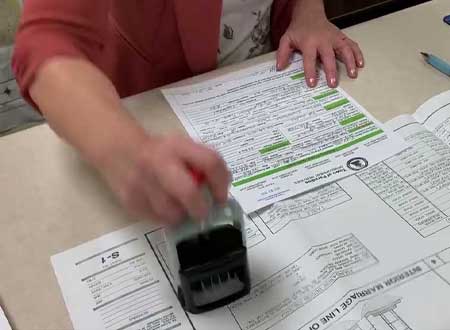
Shed Electrical Permits & Local AHJ Code Compliance Requirements
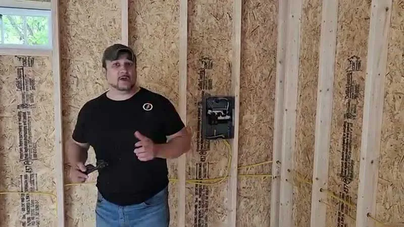
Dealing with the local authority having jurisdiction (AHJ) tests your patience faster than pulling sticky copper wire through a tight PVC sweep.
Skipping a permit to save a few hundred dollars can come back to haunt you when you sell your home.
An inspector may flag the unpermitted underground electrical work, forcing you to fix it before the deal can move forward.
Getting the permit right takes care and attention to detail, especially when preparing the load calculation and site plan.
A rough sketch is not enough. Plan reviewers need accurate information about where the wiring runs and how deep it will be buried.
And local rules can be stricter than the national code. If your city requires rigid metal conduit under a driveway and you discover that after the concrete is poured, you could be facing a costly rework.
Futureproofing Shed Subpanel for Property Value
Your home’s next buyer might transform a basic storage shed into a home office or high-draw EV charging bay. Pulling a flimsy half-inch PVC pipe out to the shed locks you into a dead-end setup that prevents ever upgrading amperage without tearing up your lawn.
A safe shed electrical system should be easy to inspect, with accessible junction boxes and a clearly labeled subpanel.
That attention to detail shows inspectors and future buyers that safety mattered more than taking shortcuts.
And if your detached shed still relies on an outdated three-wire feeder from the home’s main panel, you’re putting the property at unnecessary electrical risk and may not meet current code requirements.
Power Requirements for High-Draw Tools and Compressors
Compressors and table saws can demand far more power the moment they start than they use while running.
A 3-horsepower compressor rated at 15 amps can briefly surge to around 60 amps at startup, creating a sudden voltage drop if the feeder is undersized.
That drop can stall the motor, trip the breaker, and leave you wondering why equipment that worked fine yesterday suddenly will not start.
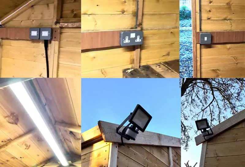
Balancing 120V and 240V Equipment Loads
When sizing a shed or workshop electrical system, account for lighting and the largest motor startup demand, and apply a 125% factor. This allows handling continuous heavy loads.
A properly balanced 120V/240V subpanel helps keep voltage stable. While dedicated 240V circuits let heavy equipment draw the same power at half the amperage of 120V operation, reducing heat in the wiring and helping motors run more efficiently.
Single 120V Branch Circuit vs. 240V Subpanel: Which Do You Need?
I was once rushing to finish a shed wiring project on a tight budget when I convinced myself that a single 20-amp multi-wire branch circuit from the house would be enough.
I figured I could simply alternate between the dust collector and table saw. I never imagined they could demand power at exactly the wrong moment.
Then, during a late-night furniture build, a thick piece of hard maple bound in the saw just as the dust collector kicked on, overloading the shared neutral and sending a voltage surge through the line that fried my $400 lathe speed controller.
The surge also tripped the garage breaker in a blinding flash, leaving me to trace a shared-neutral fault through 100 feet of underground wiring.
That night taught me a brutal lesson: trying to save a few dollars by skipping a proper subpanel can cost far more in damaged equipment and lost time.
Single Branch Circuit Limitations and Multi-Wire Options
A shed can quickly outgrow a single circuit once you add power tools, lighting, or equipment.
A multi-wire branch circuit can deliver two 120-volt circuits using a shared neutral and two hot wires. Both hot wires must disconnect together, so this setup requires a double-pole breaker or approved handle tie.
You generally cannot run multiple separate circuits from the house to the same detached shed unless a specific exception applies. Running two 120-volt lines from different breakers into the shed can create a serious safety problem.
Sizing a Dedicated Subpanel for Workshop Expansion
Installing a 60-amp or 100-amp subpanel provides an isolated distribution point directly inside the shed.
A properly sized subpanel gives your shed its own electrical distribution point. If a breaker trips, you can reset it inside the shed instead of walking through the rain back to the house.
40-Amp Subpanel: Sufficient for basic 120V lighting, small hand tools, and a modest 240V air compressor running individually.
60-Amp Subpanel: The sweet spot for single-person woodworking shops using a table saw, dust collector, and localized space heating simultaneously.
100-Amp Subpanel: Necessary for heavy fabrication shops running MIG/TIG welders, CNC machinery, and high-draw climate control systems.
Installing a main-lug subpanel without an integrated main disconnect switch inside a detached outbuilding violates code if the panel houses more than six circuit breakers.
Use a main-breaker subpanel or add a separate disconnect switch right where the feeder enters the building.
NEC Code Requirements for Shed Subpanels (Articles 225 & 250)
Wiring a detached building comes under distinct sections of NEC Article 225 and Article 250, and getting them wrong can put your shed and your safety at risk.
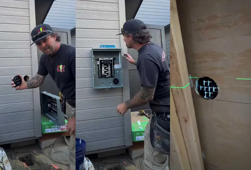
Subpanel Working Clearance Mandates (NEC 110.26)
Width Clearance: Minimum 30 inches wide (or the width of the equipment, whichever is greater).
Frontal Clearance: Minimum 36 inches of clear, unobstructed depth in front of the panel face.
Headroom Clearance: Minimum 6.5 feet of vertical clear space from the floor up.
Storage Rule: Zero clutter, wood piles, or workbenches allowed within this boundary.
Stacking wood piles, toolboxes, or shelving directly beneath the subpanel violates core safety rules.
Auxiliary Grounding Electrode Systems
Textbook diagrams often show grounding rods driven straight down into loose dirt. Real-world rocky soil makes driving an 8-foot steel rod straight down almost impossible.
Code allows driving rods at an angle up to 45 degrees, or burying them flat in a 30-inch-deep trench when striking solid bedrock.
For a detached structure with a subpanel, the grounding electrode system connects directly to the panel’s ground bus, with two 8-foot copper-clad rods installed at least 6 feet apart and connected with an unbroken #6 AWG copper conductor.
Ground rods do not trip circuit breakers during a short circuit; they stabilize system voltages during nearby lightning strikes and dissipate ambient static buildup.
Planning the Feeder Route & Trench Excavation
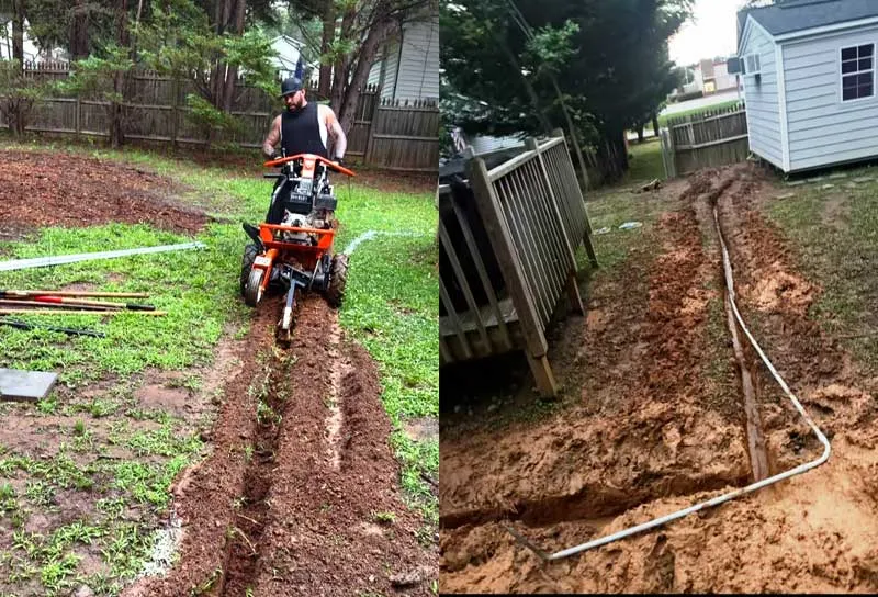
Call 811 to locate underground utilities. This is the non-negotiable first step of any digging project.
Mark the gas, telecommunications, water, and primary electric lines using high-visibility spray paint and flags.
Main House Exit: Establish a clean rim-joist penetration point away from hose bibs and structural posts.
Utility Clearance: Maintain a minimum 12-inch clear distance when crossing existing gas or water lines.
Path Pivot: Use broad 90-degree sweep elbows instead of tight bends to ease wire pulling.
Canopy Bypass: Swing paths outside the primary drip-line of mature trees to prevent root damage.
Shed Inlet: Terminal penetration point through exterior wall into the disconnect or subpanel.
Trench Layout and Entry Penetrations
Lay heavy blue tarps along the trench path before digging. Piling excavated dirt onto tarps keeps lawn grass clean and speeds up backfilling, cutting cleanup time in half.
Layout string lines mark the excavation path before removing sod. Digging trenches with a subtle slope away from foundation walls prevents rainwater from pooling near house footings.
Wall penetrations require heavy-duty LB conduit bodies paired with expansion couplings to handle seasonal ground settling. Expansion couplings prevent frost heave from pulling conduit bodies apart or tearing subpanels right off the studs during deep winter freeze cycles.
Rent a walk-behind hydraulic trenching machine for runs longer than 30 feet.
Paying $150 for a four-hour power trencher rental saves days of backbreaking hand-shoveling, producing a clean, level 4-inch-wide trench at exact code depth.
Backfill Layer Profile (Bottom to Top)
Base Layer: 2 inches of compacted washed masonry sand bedding.
Wiring Layer: Conduit or UF-B direct burial cable resting flat on the sand bed.
Cushion Layer: 2 inches of sand cover poured directly over the conduit or cable.
Sub-Backfill: Compacted native backfill dirt filled up to half total trench depth.
Warning Layer: Bright yellow electrical warning tape laid continuously 12 inches above the conduit line.
Surface Layer: Compacted topsoil and sod layer brought level with surrounding grade.
Direct Burial UF-B Cable vs. PVC Schedule 40/80 vs. RMC Conduit
UF-B Direct Burial: Simple to Install, Easy to Get Wrong
Underground Feeder (UF-B) cable offers a simple solution for short, low-amperage installations.
Its solid vinyl sheath encapsulates individual copper conductors, making it completely moisture-resistant.
Direct burial cables remain vulnerable to rodent damage and accidental shovel strikes.
PVC Schedule 40/80 vs. Metallic Systems
PVC conduit systems resist corrosion and deliver long-lasting underground protection. Schedule 40 PVC works great for underground horizontal runs, while Schedule 80 PVC provides thick-walled impact resistance for exposed vertical risers above ground.
Schedule 40 PVC: Standard wall thickness optimized for structural rigidity under subterranean soil compaction. Restricted to underground runs or concealed areas.
Schedule 80 PVC: Extra-thick heavy-duty wall profile designed to resist severe physical impacts. Mandated for all exposed vertical risers rising out of the ground.
Rigid Metal Conduit (RMC) delivers maximum physical protection, requiring only 6 inches of soil cover. Threading and bending heavy galvanized steel pipe, however, demands specialized pipe tools and significant installation labor.
Navigating Tree Roots, Rocks & Driveways When Trenching
When you strike impenetrable shelf rock or massive tree roots you need an alternative installation strategy.
Years ago, an attempt to force a trenching machine through an oak tree’s primary root system to save twenty minutes resulted in disaster.
The machine kicked back wildly, tore up the drive tracks, and killed a mature oak tree two seasons later.
Tunneling under major roots or routing around the tree canopy takes extra time up front, but saves thousands in property damage later.
Tree Root Bypass Strategy
Trench normally up to the canopy drip-line of the tree.
Stop machine trenching upon encountering structural roots larger than 2 inches in diameter.
Hand-tunnel beneath major roots using a long steel wrecking bar or hydro-bore pipe.
Push a protective PVC conduit sleeve through the bore hole to house the feeder line without harming root systems.
Another option involves switching to Rigid Metal Conduit (RMC), which requires only 6 inches of soil cover. This cuts down on deep rock chipping while keeping the installation completely safe and code-compliant.
Driveways present a similar challenge.
Water-jet hydro-boring uses high-pressure water connected to a rigid PVC pipe to blast a clean hole through packed dirt right under concrete slabs, avoiding costly concrete demolition.
Wire Gauge Requirements To Prevent Severe Long-Distance Voltage Drop
If you run equipment under low voltage it causes motors to overheat and fail early.
National electrical guidelines recommend keeping voltage drop across branch feeders under 3 percent for maximum efficiency.
Operating a 120V system with more than a 3.6V drop (below 116.4V under full load) starves tools of necessary power.
Aluminum MHF cable often outperforms copper on long underground runs purely on cost efficiency.
Purchasing larger #2 AWG aluminum cable paired with heavy-duty dual-rated lugs costs roughly half as much as equivalent #4 AWG copper wire, delivering clean, reliable power while keeping project expenses manageable.
When Voltage Drop Starts Hurting Performance
Optimal Operating Zone (0.0V to 3.6V Drop): Delivers 116.4V to 120.0V to equipment terminals. Motors run cool and operate at full rated power.
Critical Fault Zone (Greater than 3.6V Drop): Terminal voltage drops below 116.4V under load. Causes motor stalling, thermal cutout trips, and premature winding breakdown.
Choose the Right Copper Wire to Prevent Voltage Drops
0 to 70 Feet: #12 AWG Copper wire maintains adequate terminal voltage.
71 to 110 Feet: #10 AWG Copper wire required to offset increasing line resistance.
111 to 175 Feet: #8 AWG Copper wire required for safe motor operation.
Distance calculations must measure the entire wire path from the main house breakers, down the trench, up into the subpanel, and out to the furthest receptacle.
Compensating for long runs requires stepping up conductor sizes beyond basic amperage table recommendations.
When installing a 240V, 60-amp subpanel at 150 feet, move up from standard #6 AWG copper to #4 AWG copper or switch to #2 AWG Mobile Home Feed (MHF) aluminum to maintain full operational voltage.
Mastering Subpanel Installation: Grounding Rods and Neutral Bonding
The main service panel bonds the neutral and ground together at the primary supply point.
A detached shed subpanel is different because its neutral bar must remain completely isolated from ground.
Inside the shed subpanel, remove the green bonding screw or strap that connects the neutral bus to the metal enclosure.
This ensures neutral current returns to the main panel only through the insulated neutral conductor, rather than flowing through the ground wire or the subpanel box.
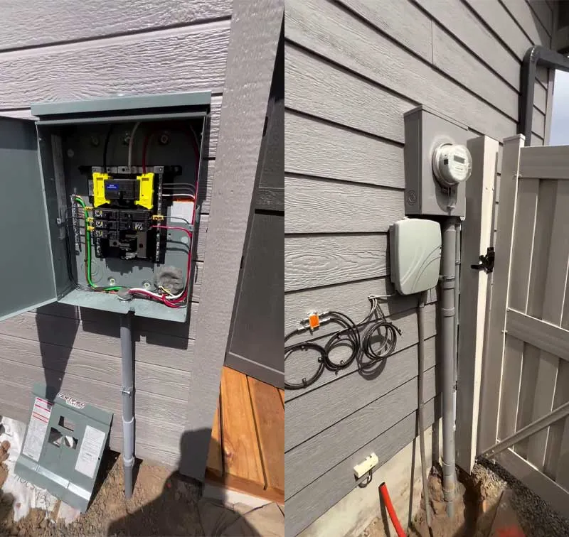
Driving Auxiliary Grounding Electrodes
Run an unbroken #6 AWG copper grounding electrode conductor from the subpanel’s ground bar to two exterior ground rods driven 8 feet deep into the earth.
Secure the grounding electrode conductor to each rod using direct-burial rated bronze clamps (often called acorns). Inspect these connections to ensure tight metal-to-metal contact before backfilling the installation.
Advanced Ground Fault (GFCI) and Arc Fault (AFCI) Safeguards in Damp Outbuildings
Unheated sheds battle brutal humidity shifts and heavy condensation.
Add solid GFCI and AFCI safeguards to stop dangerous electrical shocks and prevent hidden fire hazards in damp spaces.
Installing a GFCI breaker inside the subpanel protects the entire branch circuit from start to finish.
Alternatively, wiring a GFCI receptacle as the first device on a circuit protects all downstream standard outlets connected to its load terminals.
Two Paths for Ground Fault Protection
Option A (Panel-Level Protection): Install a GFCI circuit breaker inside the subpanel. This safeguards the entire circuit length, including all junction boxes and downstream receptacles.
Option B (Device-Level Protection): Install a standard breaker in the subpanel, feed a GFCI receptacle at the first outlet position (LINE terminals), and daisy-chain remaining standard outlets from its LOAD terminals.
Arc Fault Protection: Don’t Let One Spark Start a Fire
AFCI breakers protect against a hidden danger: electrical fires caused by low-level arcing from pinched wires, loose terminal screws, or damaged tool cords.
AFCI protection detects dangerous arcing and sparking inside walls or damaged cords before they can start a fire.
GFCI protection looks for tiny amounts of electrical current escaping to ground, helping prevent serious electric shock.
Using both types of protection gives your workspace protection against both fire and shock hazards. A dual-function AFCI/GFCI breaker makes this easier by providing both protections at the panel.
If a GFCI outlet trips instantly upon powering up an air compressor, isolate the issue with these steps:
Unplug all devices from downstream receptacles.
Reset the GFCI module; if it holds, the supply wiring is healthy.
Reconnect tools one by one.
If an electric motor trips the circuit immediately, check for moisture inside the motor junction box or a degraded neutral-to-ground short inside the motor casing.
4 Common Shed Wiring Code Violations (And How to Fix Them)
Here are some of the most common wiring mistakes and how to fix them.
Mistake 1: Bonding the neutral and ground in the subpanel
This can create unwanted electrical paths through the ground wires and metal parts of the shed. To fix it, remove the green bonding screw and keep the neutral and ground bars separate in the subpanel.
Mistake 2: Burying the wire too shallow
A cable buried only 8 inches deep can easily be damaged by a shovel, lawn tool, or other digging equipment. Dig to the required depth for your wiring method, such as 18 inches for PVC conduit or 24 inches for UF-B in the example requirements.
Mistake 3: Using THHN wire in buried conduit without wet-location rating
Underground conduit can collect water, even when it looks sealed. Standard THHN alone is not rated for wet locations, so use dual-rated THHN/THWN-2 conductors instead.
Mistake 4: Skipping expansion joints on exterior PVC conduit
Ground movement and frost can put stress on rigid PVC conduit and pull on the connections. An expansion coupling can help absorb this movement and protect the conduit and junction boxes.
Final Safety Checks Before Powering the Shed
Use this checklist to evaluate the load specs and source materials before opening a trench or pulling cables.
1 – Permit & Administrative Clearance:
Local AHJ permit application submitted with site plan.
Call 811 utility markout complete (Gas, Water, Telecom clear).
Property line set-back distance verified for panel access.
2 – Load Calculation & Feeder Sizing:
Highest Starting Motor Load calculated (Amps x 1.25).
Continuous Lighting and HVAC calculated (Amps x 1.25).
Feeder Wire Selected (#12/2 UF-B, #8 AWG Cu, or #2 AWG Al).
Conduit Sizing Chosen (1/2-inch, 1-1/2-inch, or 2-inch PVC).
One-Way Run Length measured in feet.
Voltage Drop verified under 3 percent.
3 – Trenching & Conduit Specifications:
Target Burial Depth chosen (24″ for UF-B, 18″ for PVC, 6″ for RMC).
Bedding Sand Layer prepped (2 inches bottom, 2 inches top coverage).
Yellow Warning Tape placed 12 inches above conduit/cable.
Riser Pipe selected (Schedule 80 PVC fitted with Expansion Coupling).
4 – Subpanel & Grounding Audit:
Main Disconnect switch installed at entrance door location.
Green Neutral Bonding Screw REMOVED from subpanel neutral bus.
Neutral Bar ISOLATED from metal panel enclosure.
Ground Bar BONDED directly to panel enclosure.
Two 8-Foot Ground Rods driven at least 6 feet apart.
#6 AWG Solid Copper wire connected to rods via Bronze Acorn Clamps.
5 – Interior Branch Circuits & Devices:
All 120V shop receptacles GFCI protected.
EMT Conduit strapped within 3 feet of boxes and every 10 feet on runs.
Receptacles side-wired or back-clamped (NO stab-in ports used).
Receptacle terminal screws torqued to 12–14 in-lbs.
High-bay overhead lights hardwired and switched at entryway.
Completing this systematic checklist keeps a shed wiring project safe, and fully compliant with national safety standards.

Read Next
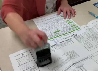 Shed Building Codes and Permit Guide For DIY Builders
 Shed Rafters vs. Trusses Comparison: Pro-Tested DIY Guide
 Cost To Build a Shed: 2026 Price Guide & DIY Budget Checklist
 Shed Roof Guide: How To Frame & Sheathe For Weatherproofing
 Shed Foundation Guide: 11 Durable Builds And Traps To Avoid
 Shed Roof Slope: Guide To Find the Right Weather-Proof Pitch
Framing-to-Finish Roadmap: DIY Guides For Every Step of The Build